
1. Įvadas
This manual provides essential information for the setup, operation, maintenance, and troubleshooting of your Digilent Arty A7-35T Artix-7 FPGA Development Board. The Arty A7-35T is designed for makers and hobbyists, offering a versatile platform for digital design and embedded systems development using Xilinx Artix-7 Field-Programmable Gate Arrays (FPGAs).
2. Produktas baigtasview
The Arty A7-35T board integrates a Xilinx Artix-7 FPGA with various peripherals and expansion options, making it suitable for a wide range of projects. Key features include:
- Xilinx Artix-7 FPGA (XC7A35T-1CSG324C)
- Multiple Pmod connectors for peripheral expansion
- Arduino/chipKIT shield connector
- Ethernet prievadas
- USB-JTAG programming port
- User LEDs, switches, and buttons
- DDR3 SDRAM

2.1 paveikslas: Iš viršaus į apačią view of the Digilent Arty A7-35T Artix-7 FPGA Development Board. This image displays the overall layout of the board, including the central Artix-7 FPGA chip, various connectors, buttons, and LEDs.

2.2 paveikslas: Detalus viršus view of the Arty A7-35T FPGA board. This image highlights the placement of the Artix-7 FPGA, Pmod headers, Arduino shield connectors, Ethernet port, and user interface components like switches and buttons.
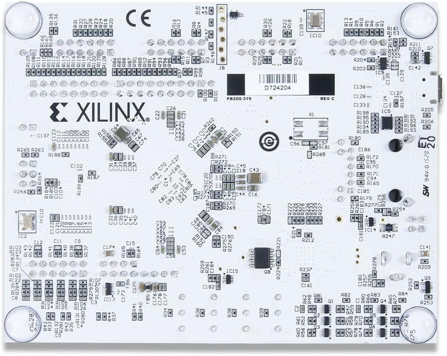
2.3 paveikslas: Apačia view of the Arty A7-35T FPGA board. This perspective shows the underside of the circuit board, revealing additional components and traces.
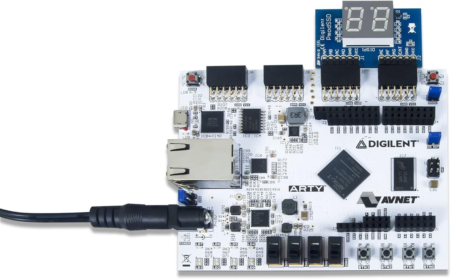
2.4 paveikslas: Arty A7-35T board demonstrating connectivity with a Digilent Pmod accessory. This image illustrates how external modules can be interfaced with the board via the Pmod headers.

2.5 paveikslas: The Arty A7-35T board in an operational state, indicated by illuminated power and user LEDs. This shows the board receiving power and potentially running a basic demonstration program.

2.6 paveikslas: Šoninis profesionalasfile of the Arty A7-35T board, showcasing the various connectors such as the power input, USB port, and Ethernet port.

2.7 paveikslas: A different side view of the Arty A7-35T board, providing a perspective on the board's height and the arrangement of its components from the side.
3. Sąranka
3.1. Išpakavimas ir patikrinimas
Carefully remove the Arty A7-35T board from its packaging. Inspect the board for any visible damage. Ensure all components are securely attached.
3.2. Maitinimo prijungimas
The Arty A7-35T can be powered via the USB port or an external 7V-15V power supply connected to the barrel jack. For stable operation, especially when using power-hungry peripherals, an external power supply is recommended.
- Connect the USB cable to the micro-USB port (J10) on the board and to your computer.
- Alternatively, connect a compatible external power supply to the barrel jack (J12).
- Ensure the power select jumper (J11) is set to the appropriate source (USB or EXT).
3.3. Programinės įrangos diegimas
To develop and program the Arty A7-35T, you will need the Xilinx Vivado Design Suite. Follow the instructions provided by Xilinx for installation. Digilent also provides board support files ir buvęsample projects for Vivado.
- Download and install Xilinx Vivado Design Suite from the Xilinx websvetainę.
- Install the Digilent board files for Arty A7, typically found on the Digilent website's resource center.
- Ensure USB drivers for the JTAG programmer are correctly installed.
4. Naudojimo instrukcijos
4.1. Įjungimas
Once connected to a power source, the power LED (LD11) should illuminate, indicating the board is receiving power. If using USB power, your computer should detect the device.
4.2. Programming the FPGA
The FPGA can be programmed using the Xilinx Vivado Design Suite via the onboard USB-JTAG programuotojas.
- Open Xilinx Vivado and create or open an FPGA project targeting the Artix-7 XC7A35T-1CSG324C.
- Generate a bitstream (.bit file) for your design.
- Use the Hardware Manager in Vivado to connect to the Arty A7 board.
- Program the device with your generated bitstream.
The FPGA can also be configured from a Quad-SPI flash memory. Refer to Digilent documentation for details on programming the flash memory.
4.3. Using Onboard Peripherals
The Arty A7-35T includes several user-configurable peripherals:
- LEDs (LD0-LD3, LD4-LD7): Eight user LEDs for visual feedback.
- Switches (SW0-SW3): Four slide switches for digital input.
- Buttons (BTN0-BTN3): Four push buttons for momentary input.
- Reset Button (CK_RST): Resets the FPGA configuration.
These peripherals are connected to specific FPGA pins and can be controlled or read from your FPGA design.
4.4. Expansion Connectors
The board features Pmod connectors and an Arduino/chipKIT shield connector for expanding functionality with various modules. Ensure proper voltage levels and pin assignments when connecting external hardware.
5. Priežiūra
5.1. Bendroji priežiūra
Handle the Arty A7-35T board with care to prevent damage from electrostatic discharge (ESD). Always hold the board by its edges. Store the board in an anti-static bag when not in use.
5.2. Valymas
Jei reikia, švelniai nuvalykite lentą minkštu, sausu šepečiu arba suslėgtu oru, kad pašalintumėte dulkes. Venkite naudoti skysčius ar abrazyvines medžiagas.
5.3. Firmware atnaujinimai
Periodically check the Digilent website for any firmware updates for the onboard USB-JTAG programmer or other components. Follow the provided instructions carefully for any update procedures.
6. Problemų sprendimas
6.1. Maitinimo problemos
- No Power LED (LD11): Check power source connection (USB or external adapter) and ensure the power select jumper (J11) is correctly set. Verify the external power supply provides 7V-15V.
6.2. USB Connectivity Problems
- Kompiuteris neaptiko plokštės: Ensure USB cable is securely connected. Try a different USB port or cable. Verify that the necessary USB drivers for the Digilent JTAG programmer are installed on your computer.
6.3. FPGA Programming Errors
- Vivado Hardware Manager cannot find device: Confirm USB connection and driver installation. Ensure the board is powered on. Check that the correct device (Artix-7 XC7A35T) is selected in your Vivado project.
- Programming fails: Verify your bitstream is correctly generated and compatible with the Artix-7 FPGA. Ensure no other software is interfering with the JTAG ryšį.
6.4. Unexpected Behavior
- Design not functioning as expected: Review your HDL code and constraints. Use Vivado's debugging tools (e.g., ILA, VIO) to inspect internal signals.
- Board becomes unresponsive: Press the CK_RST button to reset the FPGA configuration. If issues persist, power cycle the board.
7. Specifikacijos
| Funkcija | Vertė |
|---|---|
| Prekės ženklas | Digilent |
| Modelio pavadinimas | 410-319-1 |
| FPGA | Xilinx Artix-7 (XC7A35T-1CSG324C) |
| RAM | LPDDR |
| Atminties greitis | 667 MHz |
| Įdiegtos RAM atminties dydis | 256 MB |
| Atminties talpa | 256 MB |
| Ryšio technologija | Ethernet |
| Operacinės sistemos suderinamumas | Linux (and Windows/macOS with Vivado) |
| Prekės svoris | 0.705 uncijos |
| Gaminio matmenys (IxPxH) | 4 x 3 x 1 colio |
| Gamintojas | Digilent |
| Pasiekiama pirmoji data | 29 m. spalio 2015 d |
7.1. Kas yra dėžutėje
- Digilent Arty A7-35T Artix-7 FPGA Development Board
- Access to 2 free eBooks: IDD VHDL Edition and Real Digital book
8. Informacija apie garantiją
For detailed warranty information regarding your Digilent Arty A7-35T Artix-7 FPGA Development Board, please refer to the official Digilent website or contact Digilent customer support directly. Warranty terms and conditions may vary by region and purchase location.
9. Parama
For further assistance, technical documentation, tutorials, and community forums, please visit the official Digilent websvetainė:
- Digilent Websvetainė: https://digilent.com/
- Product Resource Center: Look for the Arty A7-35T on the Digilent website for specific documentation, schematics, and example projektus.
- Bendruomenės forumai: Engage with other users and Digilent engineers for support and project ideas.
Taip pat galite apsilankyti Digilent Store on Amazon dėl informacijos apie produktą ir susijusius elementus.


