
Malahit ATU-100
Malahit ATU-100 Automatic Antenna Tuner DIY Kit User Manual
Brand: Malahit | Model: ATU-100
1. Įvadas
The Malahit ATU-100 is a Do-It-Yourself (DIY) kit for an automatic antenna tuner, designed by N7DDC. This kit is intended for amateur radio enthusiasts who wish to assemble their own high-quality antenna tuning unit. It features a 0.96-inch OLED screen for clear data display and comes with the latest 3.2 version firmware pre-programmed. The tuner is designed to operate across a wide frequency range of 1.8-50MHz, automatically matching antenna impedance to optimize radio performance.
2. Sąranka ir surinkimas
This section provides detailed instructions for assembling your ATU-100 kit. While the kit includes pre-soldered SMD components and chips, careful attention to detail is required for successful assembly of the remaining parts.
2.1 Rinkinio turinys
Before beginning assembly, verify that all components listed below are present in your kit. Refer to the image for a visual representation of the kit contents.

Vaizdas: Viršview of all components included in the Malahit ATU-100 DIY kit, featuring the PCB, toroids, relays, OLED display, wires, and various electronic parts.
- Printed Circuit Board (PCB) with pre-soldered SMD components
- Toroid cores (various sizes for inductors)
- Relays (multiple units)
- 0.96-inch OLED Display module
- Capacitors (through-hole and high-voltage SMD)
- Inductor wires (enameled copper wire)
- Connectors (power jack, coax connectors)
- Push buttons and switches
- Jumper wires and header pins
- Diodes and other discrete components
2.2 Reikalingi įrankiai
Surinkimui rekomenduojami šie įrankiai:
- Soldering Iron with a fine tip
- Solder (rosin core, electronics grade)
- Vielos pjovikliai/nuėmikliai
- Small Pliers (needle-nose recommended)
- Magnifying Glass or Loupe (highly recommended for small components)
- Multimeter (for continuity checks)
- Small diameter rods (e.g., Allen wrenches) for winding coils (4mm and 6mm recommended)
- Electrical Tape or insulating material (if using a metal enclosure)
2.3 Surinkimo žingsniai
Follow these steps carefully to assemble your ATU-100. It is crucial to take your time and verify each step before proceeding.
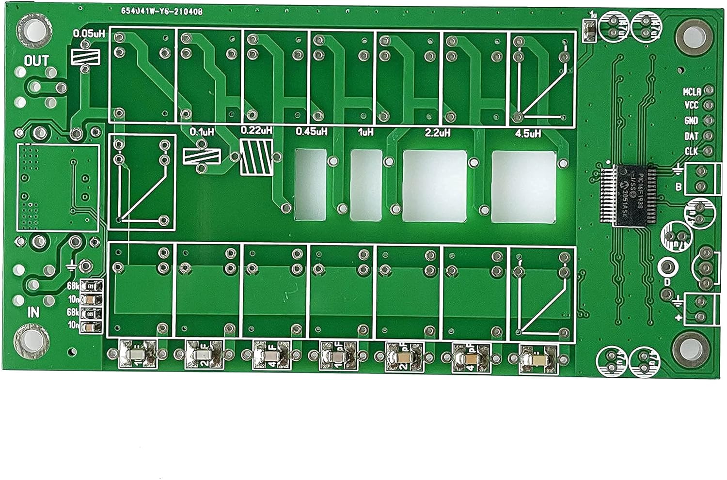
Vaizdas: Stambus planas view of the ATU-100 Printed Circuit Board (PCB), showing component outlines and connection points.
- Paruoškite PCB: Ensure the PCB is clean and free of debris. All Surface Mount Device (SMD) components should already be soldered in place.
- Wind the Toroids: Tai yra labai svarbus žingsnis.
- Refer to the provided instruction sheet for specific wire lengths and winding turns for each toroid.
- For the binocular core (tandem match transformer), ensure correct wire routing. The four small holes just outside the binocular toroid's diagram on the PCB are for these connections.
- Use appropriate diameter rods (e.g., 4mm and 6mm Allen wrenches) to wind the air core inductors.
- It is recommended to wind and install the toroids prieš soldering the relays, as this provides more working space.
- Ensure the enamel insulation is removed from the ends of the wires before soldering. A hot soldering iron can help burn off the varnish.
- Install Relays: Carefully insert and solder all relays into their designated positions on the PCB. Ensure correct orientation.
- Install Capacitors: Solder the through-hole capacitors. Pay close attention to the polarity of electrolytic capacitors; the marked side on the capacitor should align with the white mark on the PCB's silkscreen.
- Install Diodes: Solder any remaining diodes. For vertically installed diodes, ensure the white ring mark on the diode aligns with the marking on the PCB.
- Connect the OLED Display:
- Before soldering the slip-on terminals to the OLED module, make a diagram of the pinout (Gnd, VCC, SCL, SDA) as these markings may become obscured.
- Connect the OLED display to the PCB using the provided wires, ensuring correct pin alignment.
- Connect Switches and Buttons:
- Wire the Auto, BYP (Bypass), and Tune switches to the PCB. Note that the wire connecting half of the Auto, BYP, and Tune switches typically goes to GROUND, not the positive (+) wire, as might be mistakenly depicted in some generic diagrams. The other side of the Tune switch receives the positive wire.
- Use appropriate wire gauges. For initial power connections, 18 AWG stranded insulated wire may be used, but smaller gauges (e.g., 22 AWG stranded insulated wire) are necessary for other connections, especially for the small PCB holes for Auto and BYP switches.
- Maitinimo jungtys: Connect the power input jack and any on/off switch wiring. Ensure correct polarity for the power supply.
- Coax Connectors: Solder the input ("IN") and output ("OUT") coax connectors to the PCB. Double-check that the center pin connects to the signal trace and the outer shield connects to ground.
- Galutinė apžiūra: After all components are soldered, perform a thorough visual inspection for:
- Cold solder joints or solder bridges.
- Correct component orientation (diodes, capacitors, relays).
- Proper wire routing and secure connections.
- No short circuits, especially if installing into a metal enclosure. Consider adding electrical tape or insulation to the inside of the enclosure where solder points might contact the metal.

Image: A fully assembled Malahit ATU-100 unit, showcasing the PCB, toroids, relays, and the connected OLED display showing operational parameters.

Paveikslėlis: Sujungtas view showing the schematic diagram of the ATU-100 and a detailed image of the assembled unit, useful for understanding component placement and connections.
3. Naudojimo instrukcijos
Once assembled and connected to your radio and antenna, the ATU-100 is designed for straightforward operation.
- Maitinimas: Connect a 10-15 VDC power supply to the tuner. The OLED display should illuminate.
- Prijunkite įrangą: Connect your radio's antenna output to the "IN" port of the ATU-100 and your antenna to the "OUT" port.
- Automatinis derinimas: The ATU-100 is an automatic tuner. When RF power is applied (e.g., by transmitting a low-power carrier), the tuner will automatically begin the tuning process to achieve the lowest possible Standing Wave Ratio (SWR).
- Monitoriaus ekranas: The OLED display will show key parameters such as:
- PWR: Transmitted power in Watts.
- SWR: Standing Wave Ratio. The goal is to achieve an SWR close to 1.0.
- L: Inductance value in microhenries (uH).
- C: Capacitance value in picofarads (pF).
- Manual Tuning (if applicable): While primarily automatic, some versions or configurations may allow for manual adjustments or bypass modes via the dedicated buttons. Refer to the specific firmware documentation for advanced features.
- Rekomenduojama galia: While tuning, it is recommended to use a maximum power of 30 watts. After tuning is complete and a low SWR is achieved, the tuner can handle up to 100 watts for operation.
4. Priežiūra
The ATU-100 is a robust device, but proper care ensures its longevity and performance.
- Laikyti švarų: Regularly clean the exterior of the tuner with a soft, dry cloth. Avoid using harsh chemicals or abrasive materials.
- Apsaugokite nuo elementų: Keep the tuner away from moisture, extreme temperatures, and direct sunlight.
- Patikrinkite jungtis: Periodically check all soldered connections and wiring for any signs of wear or looseness.
- Firmware atnaujinimai: If new firmware versions become available, follow the manufacturer's instructions for updating. The kit comes with version 3.2 pre-programmed.
5. Problemų sprendimas
If you encounter issues with your ATU-100, consider the following common problems and solutions:
| Problema | Galima priežastis | Sprendimas |
|---|---|---|
| No display / Relays constantly click | Incorrect wiring, power supply issue, or assembly error. |
|
| Tuner not matching / High SWR | Incorrect antenna connection, faulty components, or insufficient power for tuning. |
|
| Pertraukiamas veikimas | Loose connections or cold solder joints. |
|
6. Specifikacijos
Key technical specifications for the Malahit ATU-100 Automatic Antenna Tuner:
| Parametras | Vertė |
|---|---|
| Maitinimo šaltinis | 10-15 VDC |
| Maksimali srovė | 450 mA |
| Maksimali darbinė galia | 100 vatų |
| Max Measured Power | 150 vatų |
| Minimum Power for Tuning Start | 1 vatų |
| Recommended Max Power While Tuning | Not above 30 watts |
| Minimum Measured Power | 0.1 vatų |
| Step for Measurement (under 10W) | 0.1 vatų |
| Step for Measurement (above 10W) | 1 vatų |
| Galios matavimo tikslumas | 10 % |
| Maximum Inductance Set | 8.5 uH |
| Minimal Step for Setting Inductance | 0.1 uH |
| Maximum Installed Capacity | 1870 pF |
| Minimal Step for Setting Capacity | 10 pF |
| Gaminio matmenys | 5.9 x 3.9 x 1.9 colio |
| Prekės svoris | 8.8 uncijos |
| Dažnių diapazonas | 1.8-50MHz |
| Varža | 50 omų |
7. Palaikymas ir garantija
For technical support, questions regarding assembly, or warranty information, please contact the seller or manufacturer directly. Refer to your purchase documentation for specific contact details.
As this is a DIY kit, successful operation is dependent on correct assembly. While the kit includes high-quality components, the manufacturer is not responsible for issues arising from incorrect assembly or modification.
Ask a question about this manual
Ask about setup, troubleshooting, compatibility, parts, safety, or missing instructions. Manuals+ will review the question and use this page’s manual context to help answer it.