
1. Įvadas
The UNI-T UT526 is a multifunction electrical installation tester designed for comprehensive electrical system analysis. It accurately measures insulation resistance, RCD (Residual Current Device) status, low resistance continuity, and AC/DC voltage. This device is suitable for testing power distribution systems, lightning protection systems, and wiring systems to ensure safe operation and compliance with electrical standards.

1 pav.: priekis view of the UNI-T UT526 Multifunction Electrical Installation Tester.
2. Saugos informacija
Before operating the UT526, read and understand all safety warnings and operating instructions. Failure to follow these instructions may result in electric shock, fire, or serious injury. Keep this manual for future reference.
- Prieš naudodami visada įsitikinkite, kad prietaisas yra geros darbinės būklės.
- Do not use the tester if it appears damaged or if the test leads are compromised.
- Verify the correct function of the tester on a known voltage šaltinis prieš ir po naudojimo.
- Adhere to all local and national safety codes.
- Dėvėkite tinkamas asmenines apsaugos priemones (AAP), įskaitant apsauginius akinius ir izoliuotas pirštines.
- Avoid working alone when performing electrical tests.
- Do not exceed the maximum input ratings for any function.
- Ensure the circuit under test is de-energized and locked out before making connections for resistance or continuity measurements.
3. Pakuotės turinys
Carefully unpack the box and ensure all items listed below are present and undamaged. If any item is missing or damaged, contact your supplier immediately.
- 1 x UT526 Earth Resistance Tester
- 1 x Test Lead Set
- 1 x Alligator Clip Set
- 1 x anglų kalbos vadovas
- 1 x peties dirželis
- 1 x nešiojimo krepšys
- 1x spalvota dėžutė
Note: Batteries are not included and must be purchased separately (1.5V AA batteries x 6).
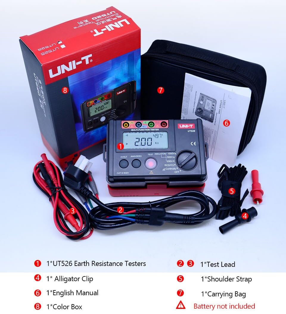
Figure 2: Included components of the UT526 package.
4. Produkto ypatybės
The UNI-T UT526 offers a range of features for reliable electrical installation testing:
- Rodyti skaičius: 10000 for precise readings.
- Rankinis diapazonas: Allows for specific range selection.
- Phase Switch (RCD): Supports 0° and 180° phase testing.
- Išsikrovusio akumuliatoriaus indikatorius: Įspėja, kai reikia pakeisti baterijas.
- Automatinis AC/DC garsumo reguliavimastage Identifikavimas: Simplifies voltage išmatavimai.
- Red Warning Lights: Visual alert for hazardous conditions.
- Sertifikatai: CE, UKCA compliant.
5. Sąranka
Before first use, install the batteries and prepare the test leads.
5.1 Akumuliatoriaus įdėjimas
- Raskite baterijų skyrių įrenginio gale.
- Atsuktuvu atidarykite akumuliatoriaus dangtelį.
- Insert 6 x 1.5V AA batteries, observing the correct polarity.
- Uždėkite akumuliatoriaus dangtelį ir pritvirtinkite varžtu.
5.2 Bandymo laidų prijungimas
Connect the test leads to the appropriate input terminals on the UT526. The terminals are color-coded and labeled for clarity (e.g., LINE, N, E, L).
6. Naudojimo instrukcijos
The UT526 offers various measurement functions. Select the desired function using the rotary switch.
6.1 Measuring Insulation Resistance
This function measures the insulation resistance of electrical circuits and equipment.
- Turn the rotary switch to one of the insulation test voltage settings: 100V, 250V, 500V, or 1000V.
- Insert test leads into the input terminals (Red to LINE, Black to N) and connect them to the circuit under test. High voltage yra išvedamas iš LINE terminalo.
- For continuous measurement, press the TESTAS button. The tester will self-lock, output the test voltage, and emit a warning light simultaneously.
- Once the measurement is finished, press TESTAS again to unlock and stop the continuous measurement.
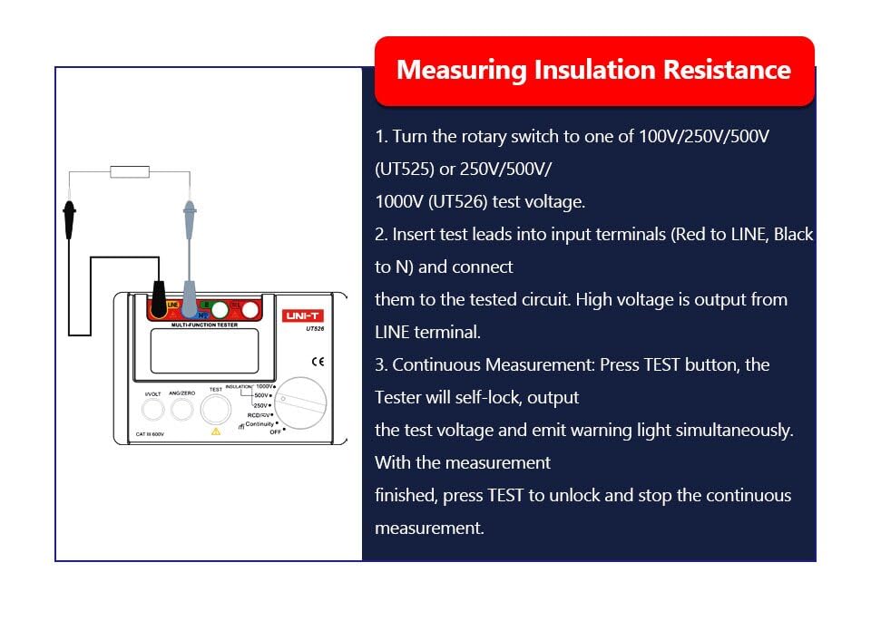
Figure 3: Setup for measuring insulation resistance.
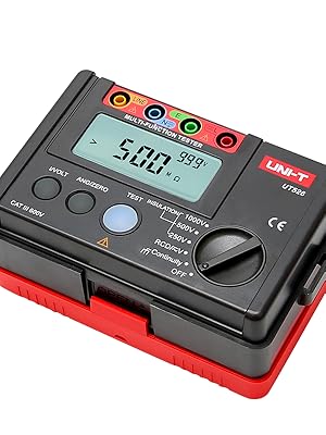
Figure 4: UT526 performing an insulation resistance test with warning light activated.
6.2 RCD Test (Residual Current Device)
The RCD test function verifies the proper operation of Residual Current Devices, ensuring they trip within specified parameters.
- Turn the rotary switch to the RCD function.
- Connect the test leads to the appropriate terminals of the RCD or circuit.
- Select the desired test current and phase (0° or 180°) using the function buttons.
- Initiate the test. The device will measure the trip time and display the result.
Video 1: Demonstration of the RCD test function using the UNI-T UT526. This video shows the connection and operation of the RCD test, illustrating how the device measures the trip time of a residual current device.

Figure 5: UT526 connected for an RCD test.
6.3 Low Resistance Continuity Measurement
This function checks for continuity in circuits and measures low resistance values.
- Turn the rotary switch to the Continuity function.
- Connect the test leads across the component or circuit to be tested.
- The display will show the resistance value. An audible beep indicates continuity (typically below a certain resistance threshold).

Figure 6: UT526 performing a low resistance continuity test on a motor.
6.4 AC/DC ttage Matavimas
The UT526 can measure both AC and DC voltages.
- Turn the rotary switch to the V (Voltage) function. The device will automatically identify AC or DC voltage.
- Connect the test leads in parallel with the circuit or component where voltage turi būti išmatuotas.
- Ekrane bus rodomas išmatuotas tūristage vertė.
6.5 Ground Resistance Measurement
While the UT526 is primarily a multifunction electrical installation tester, it also supports ground resistance measurements.
- Turn the rotary switch to the appropriate ground resistance setting (if available, or use continuity for basic checks).
- Connect the test leads according to the specific ground resistance testing method (e.g., 3-pole or 4-pole method, if supported by the model).
- Initiate the measurement and read the ground resistance value from the display.

Figure 7: UT526 connected for ground resistance testing.
7. Priežiūra
Proper maintenance ensures the longevity and accuracy of your UT526 tester.
- Valymas: Nuvalykite įrenginį su skelbimuamp cloth and mild detergent. Do not use abrasive cleaners or solvents. Ensure the device is dry before storage.
- Baterijos keitimas: Replace batteries promptly when the low battery indicator appears. Remove batteries if the device will not be used for an extended period to prevent leakage.
- Saugykla: Store the tester in a cool, dry place, away from direct sunlight and extreme temperatures. Use the provided carrying bag for protection.
- Kalibravimas: For professional use, periodic calibration by an authorized service center is recommended to maintain measurement accuracy.
8. Problemų sprendimas
Jei kyla problemų dėl UT526, žr. šias dažniausiai pasitaikančias problemas ir sprendimus:
| Problema | Galima priežastis | Sprendimas |
|---|---|---|
| Įrenginys neįsijungia | Išsikrovusios arba neteisingai įdėtos baterijos | Pakeiskite baterijas, užtikrindami teisingą poliškumą. |
| Netikslūs rodmenys | Poor test lead connection, out of calibration, environmental interference | Ensure secure connections. Check against a known source. Consider professional calibration. |
| RCD test fails to trip | Faulty RCD, incorrect test parameters, wiring issue | Verify RCD functionality independently. Check test current and phase settings. Inspect circuit wiring. |
| Ekrane rodoma „OL“ (perkrova) | Measurement exceeds selected range or device capability | Select a higher range or ensure the measurement is within the device's specifications. |
9. Specifikacijos
Detailed technical specifications for the UNI-T UT526 Multifunction Electrical Installation Tester are provided below.

Figure 8: Comprehensive specifications for the UT526.
| Specifikacija | Vertė |
|---|---|
| Prekės ženklas | UNI-T |
| Modelis | HY-UT526 |
| Maitinimo šaltinis | Battery Powered (6 x 1.5V AA) |
| Prekės svoris | 0.6 kg |
| Prekės matmenys | 6.5 x 4.33 x 4.72 colio |
| Specifikacija atitiko | CE, ISO 9001, RoHS, UKCA |
| Ekrano skaičius | 10000 |
| Izoliacijos varžos bandymas ttages | 100V, 250V, 500V, 1000V |
| RCD Phase Switch | 0° ir 180° |
| Išsikrovusio akumuliatoriaus indikatorius | Taip |
| Automatinis AC/DC garsumo reguliavimastage Identification | Taip |
| Raudoni įspėjamieji žibintai | Taip |
10. Garantija
The UNI-T UT526 Multifunction Electrical Installation Tester comes with a 1 metų garantija from the date of purchase. This warranty covers defects in materials and workmanship under normal use. It does not cover damage caused by misuse, accident, unauthorized modification, or neglect. Please retain your proof of purchase for warranty claims.
11. Parama
For technical assistance, troubleshooting beyond this manual, or warranty inquiries, please contact UNI-T customer support. Refer to the official UNI-T webNaujausią kontaktinę informaciją rasite svetainėje arba produkto pakuotėje.
UNI-T pareigūnas Websvetainė: www.uni-trend.com


