1. Įvadas
This manual provides detailed instructions for the installation, setup, and operation of your UHPPOTE AC/DC12-48V 2-Channel 433Mhz RF Wireless Remote Control Switch. This device is designed for various applications, including home appliances, lighting, and other electronic equipment, offering convenient wireless control. Please read this manual thoroughly before use to ensure proper functionality and safety.
2. Produktas baigtasview
The UHPPOTE 2-Channel RF Wireless Remote Control Switch is a versatile learning code receiver that allows you to control two independent channels wirelessly. Its robust design supports a wide power input range and features reliable signal transmission.
Pagrindinės funkcijos:
- Accepts wide power input range: 12-48V AC or DC.
- Wireless signal can pass through walls, floors, and doors for extended range.
- Enables remote control (on/off) of the receiver from a reliable distance.
- Learning code design allows easy matching with transmitters.
- Suitable for various applications including home appliances, lighting, and intelligent switches.

Vaizdas: Stambus planas view of the UHPPOTE 2-Channel RF Wireless Remote Control Switch circuit board, showing relays, capacitors, and connection terminals.
3. Setup and Code Learning
Before operating the switch, you must pair it with your remote control transmitter. The receiver has a 'Learning' button for this process.
Poravimo instrukcijos:
- Learning for the First Relay: Press the 'Learning' button on the receiver once. The indicator light will flash. Immediately press any button on your remote control transmitter. The indicator light on the receiver will flash 3 times quickly, confirming successful code learning for the first relay.
- Learning for the Second Relay: Press the 'Learning' button on the receiver twice. The indicator light will flash. Immediately press any other button on your remote control transmitter. The indicator light on the receiver will flash 3 times quickly, confirming successful code learning for the second relay.
Clearing Stored Codes:
To clear all previously learned codes from the receiver, press and hold the 'Learning' button until the indicator light remains steadily bright. This indicates all stored remote control pairings have been erased.
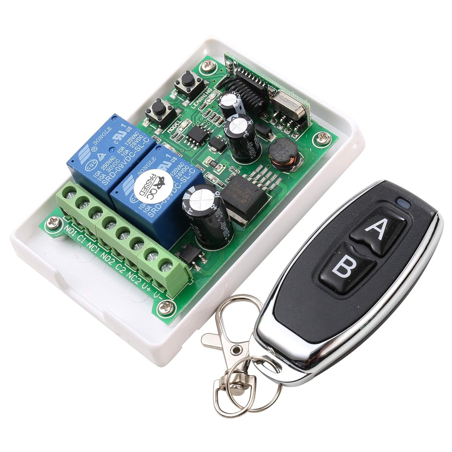
Image: The UHPPOTE 2-Channel RF Wireless Remote Control Switch module shown alongside its two-button remote control. The 'Learning' and 'Model' buttons are visible on the circuit board.
4. Veikimo režimai
The receiver supports multiple working modes, which can be selected using the 'Model' button on the circuit board. Each mode offers different control behaviors for the connected devices.
Režimo pasirinkimas:
- JOG Mode (Momentary): Press the 'Model' button once. The indicator light will flash once and then turn off. In JOG mode, the relay activates only while the remote button is pressed and deactivates upon release.
- Interlock Mode (Latched): Press the 'Model' button twice. The indicator light will flash twice and then turn off. In Interlock mode, pressing one remote button activates its corresponding relay and deactivates the other relay. Pressing the other remote button activates its relay and deactivates the first. Only one relay can be active at a time.
- Self-locking Mode (Toggle): Press the 'Model' button thrice. The indicator light will flash three times and then turn off. In Self-locking mode, each press of a remote button toggles the state of its corresponding relay (on/off).
- Delay Mode (5 Seconds): Press the 'Model' button four times. The indicator light will flash four times and then turn off. In Delay mode, activating a relay will keep it active for 5 seconds before automatically deactivating.
5. Elektros instaliacijos schemos
Proper wiring is essential for the safe and correct operation of the wireless remote control switch. Refer to the diagrams below for connecting your power source and load devices.
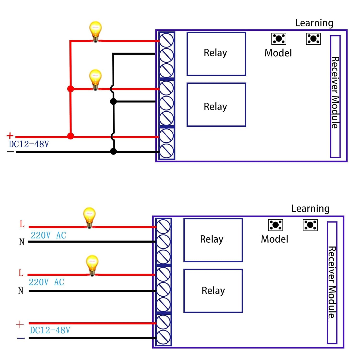
Image: Two wiring diagrams. The top diagram illustrates connections for DC loads, showing a DC12-48V power input and two independent loads connected to the NO1/C1 and NO2/C2 terminals. The bottom diagram illustrates connections for AC loads, showing a DC12-48V power input for the receiver and two independent 220V AC loads connected to the NO1/C1 and NO2/C2 terminals, with L (Live) and N (Neutral) connections.
Svarbios laidų išdėstymo pastabos:
- Užtikrinkite maitinimo šaltinio ttage matches the specifications of your load devices.
- Always disconnect power before making any wiring connections to prevent electrical shock.
- The receiver requires a DC12-48V power input for its operation.
- The relay outputs (NO1, C1, NC1, NO2, C2, NC2) are dry contacts, meaning they provide switching functionality without supplying power to the load directly. You must provide power to your load devices separately.
- Jei nesate tikri dėl kokių nors laidų prijungimo procedūrų, pasitarkite su kvalifikuotu elektriku.
6. Priežiūra
The UHPPOTE Wireless Remote Control Switch is designed for reliable operation with minimal maintenance. Follow these guidelines to ensure its longevity:
- Valymas: Įrenginį laikykite švarų, be dulkių ir šiukšlių. Valymui naudokite minkštą, sausą šluostę. Venkite naudoti skystus valiklius ar tirpiklius.
- Jungtys: Periodically check all wiring connections to ensure they are secure and free from corrosion. Loose connections can lead to intermittent operation or damage.
- Aplinka: Install the device in a dry environment, away from extreme temperatures, humidity, and direct sunlight.
- Baterijos keitimas (nuotolinio valdymo pultas): If the remote control's range decreases or it becomes unresponsive, replace its battery. Refer to the remote's specific instructions for battery type and replacement procedure.
7. Problemų sprendimas
If you encounter issues with your UHPPOTE Wireless Remote Control Switch, refer to the following troubleshooting steps:
- Device Not Responding to Remote:
- Ensure the receiver is powered on and its indicator light is active.
- Patikrinkite nuotolinio valdymo pulto bateriją ir, jei reikia, pakeiskite.
- Verify that the remote control is paired with the receiver. If not, follow the 'Setup and Code Learning' instructions.
- Ensure there are no significant obstructions or sources of strong RF interference between the remote and the receiver.
- Load Device Not Activating:
- Check all wiring connections to the load device and the receiver's output terminals.
- Confirm that the load device itself is functional and properly powered.
- Verify that the selected operating mode (JOG, Interlock, Self-locking, Delay) is appropriate for your application.
- Ensure the load's current and voltage requirements do not exceed the switch's specifications (10 Amps, 48 Volts Max).
- Operacija su pertraukomis:
- Patikrinkite, ar nėra laisvų laidų jungčių.
- Ensure the power supply to the receiver is stable and within the 12-48V AC/DC range.
- Minimize potential sources of electromagnetic interference.
8. Specifikacijos
Detailed technical specifications for the UHPPOTE AC/DC12-48V 2-Channel 433Mhz RF Wireless Remote Control Switch:
| Specifikacija | Vertė |
|---|---|
| Modelio numeris | AK-RK02E+J027 |
| Įvesties tomastage | AC / DC 12-48V |
| Veikimo dažnis | 433Mhz |
| Kanalai | 2 kanalas |
| Dabartinis reitingas | 10 Amps |
| Didžiausia perjungimo srovė | 10 Amps |
| Didžiausias perjungimo tūristage | 48 voltų |
| Minimalus perjungimo tūristage | 12 voltų |
| Jungties tipas | Sraigtinis terminalas |
| Montavimo tipas | Paviršinis montavimas |
| Veikimo režimas | Manual (via remote) |
| Gaminio matmenys | 3.5 x 2.4 x 1.1 colio |
| Prekės svoris | 4.8 uncijos |
9. Informacija apie garantiją
UHPPOTE products are manufactured to high-quality standards. This product comes with a standard manufacturer's warranty against defects in materials and workmanship. Please retain your proof of purchase for warranty claims. For specific warranty terms and conditions, refer to the documentation included with your purchase or contact UHPPOTE customer support.
10. Parama
For further assistance, technical support, or inquiries regarding your UHPPOTE AC/DC12-48V 2-Channel 433Mhz RF Wireless Remote Control Switch, please contact UHPPOTE customer service. You can typically find contact information on the product packaging or the official UHPPOTE websvetainę.
Gamintojas: UHPPOTE


