WAGO 286-364 perjungimo relės modulio naudotojo vadovas
Modelis: 286-364
1. Produktas baigtasview
The WAGO 286-364 Switching Relay Module is designed for industrial electrical applications, converting a 24VDC input signal to control a 250VAC, 5AMP output. This module is a critical component for various control systems, offering reliable switching capabilities.
Pagrindinės funkcijos:
- Įvesties tomastage: 24VDC
- Išėjimas ttage: 250VAC
- Išėjimo srovė: 5AMP
- Function: Switching Relay Module
- Category: Panel Accessories, Relay/Socket

1 pav. Baigtaview of three WAGO 286-364 Switching Relay Modules, showcasing their compact design and grey housing.
2. Sąranka ir diegimas
Proper installation is crucial for the safe and effective operation of the WAGO 286-364 module. Ensure all power sources are disconnected before beginning installation.
2.1. Montavimas
The module is designed for panel mounting. Secure it firmly using appropriate fasteners or DIN rail clips if applicable to your specific model variant. Ensure adequate ventilation around the module to prevent overheating.
2.2. Laidų jungtys
Refer to the terminal markings on the module for correct wiring. The module typically features input terminals for 24VDC control signals and output terminals for the 250VAC load.
- Prijunkite 24VDC control signal to the designated input terminals (e.g., R1+, R2-).
- Prijunkite 250VAC load to the output terminals (e.g., 13, 14).
- Įsitikinkite, kad visos jungtys yra tvirtos ir tinkamai izoliuotos, kad išvengtumėte trumpojo jungimo.

2 pav. Išsamus view of the module's connection pins, highlighting the robust design for secure wiring.

3 paveikslas: viršuje view of the modules, indicating the 'TEST' points and model number for identification and testing purposes.
3. Naudojimo instrukcijos
Once properly installed and wired, the WAGO 286-364 module operates by receiving a 24VDC signal to switch the 250VAC output. The module acts as an interface between low-voltage control circuits and higher-voltage apkrovos.
- Kai a 24VDC signal is applied to the input terminals, the internal relay will energize.
- Upon energization, the output contacts will switch, allowing the 250VAC current to flow to the connected load.
- When the 24VDC input signal is removed, the relay will de-energize, opening the output contacts and disconnecting the 250VAC load.
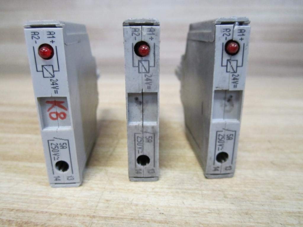
4 pav.: šonas view of the modules, showing the indicator LED which illuminates when the relay is energized, and clearly marked input/output terminals.
3.1. Indikatoriaus šviesos diodas
The module is equipped with an indicator LED (visible in Figure 4) that provides visual feedback on the relay's status. The LED illuminates when the 24VDC input signal is present and the relay is energized, confirming proper operation.
4. Priežiūra
The WAGO 286-364 Switching Relay Module is designed for long-term, maintenance-free operation under normal industrial conditions. However, periodic inspection is recommended to ensure optimal performance and safety.
- Vizuali apžiūra: Regularly check the module for any signs of physical damage, discoloration, or loose connections.
- Valymas: Jei reikia, švelniai nuvalykite modulio išorę sausa, minkšta šluoste. Nenaudokite abrazyvinių valiklių ar tirpiklių.
- Ryšio vientisumas: Periodically verify that all wiring connections are secure and free from corrosion.
Always disconnect power to the module and associated circuits before performing any maintenance or inspection.
5. Problemų sprendimas
If the WAGO 286-364 module is not functioning as expected, consider the following troubleshooting steps:
- Module Not Switching:
- Patikrinkite, ar 24VDC input signal is present and correctly wired to the input terminals.
- Check if the indicator LED on the module is illuminated when the input signal is applied. If not, there may be an issue with the input signal or the module itself.
- Nėra išėjimo galios:
- Užtikrinti, 250VAC power source for the load is active and correctly wired to the output terminals.
- Confirm that the load itself is functional and not drawing excessive current that could damage the module or trip protective devices.
- Perkaitimas:
- Check for proper ventilation around the module.
- Ensure the load current does not exceed the module's 5AMP įvertinimas.
If issues persist after following these steps, contact a qualified electrician or WAGO technical support.
6. Specifikacijos
| Atributas | Vertė |
|---|---|
| Modelio numeris | 286-364 |
| Įvesties tomastage | 24VDC |
| Išėjimas ttage | 250VAC |
| Išėjimo srovės įvertinimas | 5 Amps |
| Gamintojas | WAGO |
| ASIN | B07M93Z7W7 |
| Pirmoji laisva data | 20 m. gruodžio 2018 d |
7. Garantija ir palaikymas
Specific warranty details for the WAGO 286-364 Switching Relay Module are typically provided at the point of purchase or through official WAGO documentation. Please refer to your purchase invoice or the manufacturer's websvetainėje, kurioje pateikiama naujausia informacija apie garantiją.
For technical support, product inquiries, or assistance with troubleshooting beyond the scope of this manual, please contact WAGO directly through their official channels. Contact information can usually be found on the WAGO websvetainėje arba produkto pakuotėje.


